

Dear readers, please note that this is the old website of maxEmbedded. The articles are now no longer supported, updated and maintained. Please visit the new website here and search for this post. Alternatively, you can remove .wordpress from the address bar to reach the new location.
Example: If the website address is http://maxEmbedded.wordpress.com/contact/, then removing .wordpress from it will become http://maxEmbedded.com/contact/.
We apologize for the inconvenience. We just want to give you a better viewing and learning experience! Thanks!
In the previous post, we discussed about the basics of serial communication. In this post, we will learn about the RS-232 protocol of serial communication. This is the protocol you will be using the most when involving microcontrollers like AVR. As we proceed ahead in this post, we will deal with the concept of level conversion and towards the end, we have something interesting and practical for you – the loopback test!
Contents
RS-232 Basics
RS-232 (Recommended Standard – 232) is a standard interface approved by the Electronic Industries Association (EIA) for connecting serial devices. In other words, RS-232 is a long established standard that describes the physical interface and protocol for relatively low-speed serial data communication between computers and related devices. RS-232 is the interface that your computer uses to “talk” to and exchange data with your modem and other serial devices. The serial ports on most computers use a subset of the RS-232C standard. RS-232 protocol is mostly used over the DB9 port (commonly known as serial port), however earlier it was used over the DB25 port (also known as parallel port). We will have a look at both of them here.
RS-232 over DB-9
The pin configuration of DB-9 port is as follows. Yes, it looks exactly like (in fact it is) the serial port you would find in older computers.

RS232 DB9 Connector

DB9 Connector Pins
The pin description for the RS-232 pins is as follows:
- DTR (data terminal ready): When terminal is turned on, it sends out signal DTR to indicate that it is ready for communication.
- DSR (data set ready): When DCE is turned on and has gone through the self-test, it assert DSR to indicate that it is ready to communicate.
- RTS (request to send): When the DTE device has byte to transmit, it assert RTS to signal the modem that it has a byte of data to transmit.
- CTS (clear to send): When the modem has room for storing the data it is to receive, it sends out signal CTS to DTE to indicate that it can receive the data now.
- DCD (data carrier detect): The modem asserts signal DCD to inform the DTE that a valid carrier has been detected and that contact between it and the other modem is established.
- RI (ring indicator): An output from the modem and an input to a PC indicates that the telephone is ringing. It goes on and off in synchronous with the ringing sound.
- RxD (Received data): The RxD pin is the Data Receive pin. This is the pin where the receiver receives data.
- TxD (Transmitted data): The TxD pin is the Data Transmit pin. This is the pin through which data is transmitted to the receiver.
- GND: Ground pin.
RS-232 over DB-25
The pin configuration of DB-25 port is as follows. Yes, it looks exactly like (in fact it is) the parallel (printer) port you would find in even older computers! Even though it is called the parallel port, data transfer takes place using the serial protocol (thanks Thomas for clarification).

RS232 DB25 Connector

DB25 Connector Pins
As we can see, most of the pins are similar to that of a DB9 port. If you notice, we see that in DB25 connector there are two TxD and RxD pairs of pins. Now what does this mean? In simple words, it means that serial communication through the DB-25 connector could take place through two channels simultaneously (thanks again, Thomas!).
NOTE: Another important thing to note is that the simplest way to in which a microcontroller can communicate to a PC is through RxD, TxD, and Ground Pins. And this is what we will be doing here and hence forth in upcoming posts. The other pins are not of much use to us, for now. Now this was something about RS-232. Our next topic is level conversion. Btw, have you heard of TTL? Sounds familiar, but what is TTL? Lets read on!
Logic Level Families
By ‘Logic Level’ one means the range of voltage over which a high bit (1) and a low bit (0) is accepted in a particular IC, gate, etc. Various logic levels have been standardized, out of which the most popular ones are:
1. TTL
TTL stands for Transistor-Transistor Logic. These days TTL is the most widely used logic. TTL is mostly used in ICs and gates, like 74xx logic gates. A major drawback of the TTL logic is that most of the devices working on the TTL Logic consume a lot of current, even individual gates may draw up to 3-4 mA. In TTL Logic, a HIGH (or 1) is +5 volts, whereas a LOW (or 0) is 0 volts. But since attaining exact +5 volts and 0 volt is practically not possible every time, various IC manufactures define TTL logic level range differently, but the usual accepted range for a HIGH is within +3.5 ~ +5.0 volts, and the range for a LOW is 0 ~ +0.8 volts.
2. LVTTL
LVTTL stands for Low Voltage Transistor-Transistor Logic. LVTTL is increasingly becoming popular these days, because of the nominal HIGH voltages, and hence lesser power consumption. By lowering the power supply from 5v to 3.3v, switching power reduces by almost 60%! There are several transistors and gates, which work on LVTTL logic. Atmel’s Atmega microcontrollers are designed to work on both, LVTTL and TTL, depending upon the VCC supplied to the IC. In LVTTL Logic, a LOW is defined for voltages 0V ~ 1.2V, and High for voltages 2.2V ~ 3.3V, making 1.2V~2.2V undefined.
3. RS-232
RS232 is also one of the most popular logic. Though now quite old, it is still in use. In RS-232 logic, a HIGH (1) is represented within -3V ~ -25 V, whereas a LOW (0) is in between +3V ~ +25 V, making -3V to +3V undefined. Weird isn’t it? 😉 But that’s how it is defined! Apart from these, there are many other logic families like ECL, RTL, CMOS, LVCMOS, etc. At present, we are not much concerned about them. You can refer to this article to know more about them.
Level Conversion – TTL/RS232
So what is (logic) level conversion?? To interconnect any two logic level families, their respective HIGHs and LOWs must be same else they wouldn’t work. For example, when we want to interconnect two devices, one of which works over TTL and the other over RS232, we need to convert the HIGH of TTL (which is 3.3v~5v) into the HIGH of RS232 (which is -3v ~ -25v) and similarly, the LOW of TTL (0v~0.8v) into the low of RS232 (which is +3v ~ +25v). So you see, here lies the problem! If we do not convert the logic levels (in this case) then the LOW signal of TTL would be interpreted as a HIGH in RS232, making all the data transfer go wrong!!
The Solution
One solution is to use additional pull-up resistors, or to use Zener diodes. A better solution is the use of ICs that directly converts logic levels. Luckily logic level conversion is quite simple these days with the use of ICs like MAX232 and CP2012! We would talk about all these solutions one by one.
Zener Diodes
Zener diodes are widely used to regulate voltage between two points. When Zener diode is used in reverse bias in series with a suitable resistor, and a voltage > breakdown voltage is applied across the terminals of the Zener-resistor pair, then a voltage V = Zener Voltage appears across the terminals of the Zener diode, while the rest of the voltage appears across the terminals of the resistor. The simple circuit below shows how to use Zener diodes to convert logic levels from TTL to LVTTL (Note that this circuit is only applicable for high to low logic level conversions):

Zener Diode Circuit
Bidirectional Logic level converters are easily available in the market. Some of the websites selling them are: Adafruit, Freetronics, Sparkfun, Embedded Market etc.
IC MAX232
MAX232 ICs were invented by Maxim. These IC packages are used to convert TTL/CMOS logics to RS232 logic directly! All we need are some passive components, and we are done! Below is the circuit diagram of the MAX232 IC.
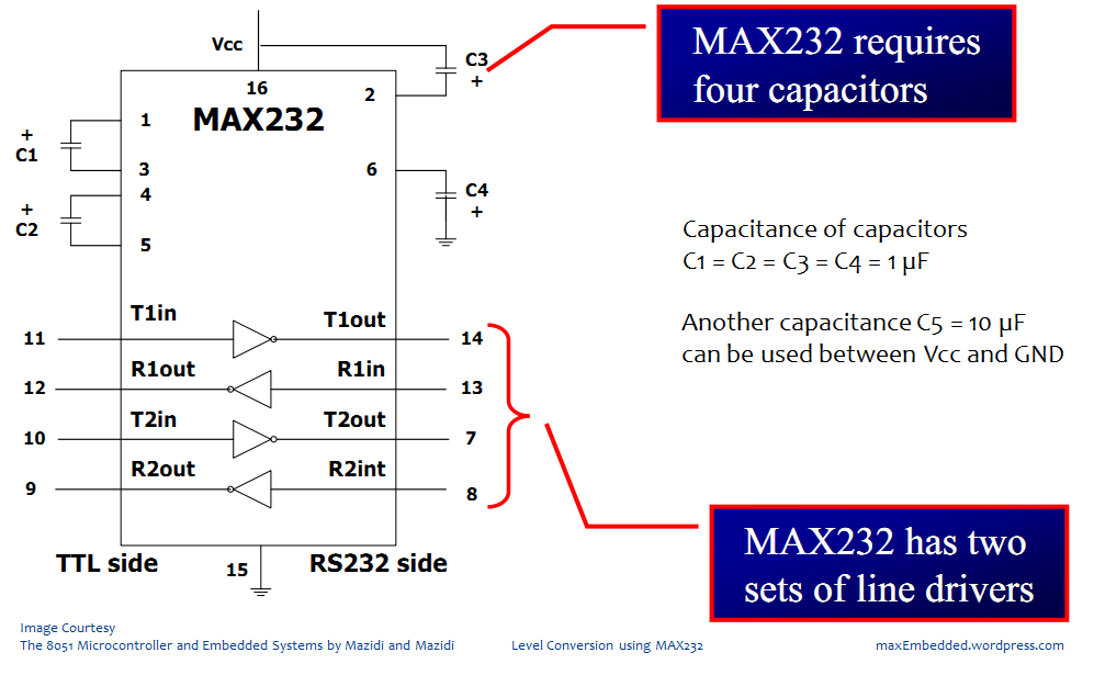
Level Conversion using MAX232
MAX232 is used to convert TTL to RS232, and vice-versa as shown in the above circuit diagram. But these days, USB is the most used protocol! Everything runs on USB – be it printer, scanner, displays or anything! But how to convert USB to UART? One way is USB → TTL → UART. The other way is to use USB-UART bridges which directly convert USB → UART. They are widely and easily available these days. Here are some of the websites: Robokits, eXtreme Electronics, Sparkfun, Adafruit etc.
All these devices work on CP210x based USB-UART conversions.
IC CP210x
CP210x is the series of ICs made by Silicon Labs. These are used to directly convert USB to UART. Below is the circuit schematic of CP2101:

CP2101 Schematics
Though these ICs are not available in DIP Packages, so it is always advisable to buy any one of the modules listed above.

This is how a CP210x based USB-UART Bridge looks like
The drivers of CP210x can be found here. They work with the Windows platform. Drivers for Mac and Linux are also available. We will discuss a little later in the same post as to how to install these drivers and work with them.
This was all about what is logic level conversion, why we need it, and how to do it. Now its enough of theoretical topics, lets have something practical stuff to do now! Next, we deal how to use the serial communication devices with your PC. So get your PC and USB-UART bridge ready! That’s all you need.
Loopback Test
A Loopback Test in serial communication is a test in which we check whether the Rx and Tx are working properly or not. How we do it? Its simple! Just short the Tx and Rx pins of the USB-UART Bridge and connect it to your PC! So it’s like transmitting data from your PC and receiving the same through the same port! Have a look at the following block diagram.

Loopback Test Setup for USB-UART Bridges

Loopback Test Block Diagram
Using a Serial Terminal at PC/Mac
So far so good. You have made the hardware connections. Now what? How do you send serial data from your PC (via USB) to any other device? Well, seems like now is time to deal with serial terminals! What is a serial terminal?
A serial terminal is an application, which allows you to directly control the serial ports of your PC/Mac i.e. it lets you send and receive data directly through your serial port. Bingo!
For various applications, it is best to have a serial terminal. For example, you want to communicate to an AVR microcontroller, or say you wanna control a microcontroller through your PC (a cool example would be control a robotic car wirelessly using your computer, it would be like real world NFS! We organized one such event last year as well !!), so how would you do that? Yes exactly! You will use a serial terminal on your PC!
Another example could be when you want to use a module, say for example, a GSM module, or a Bluetooth module with your PC. You can communicate with those modules only with the help of these serial terminals!
A number of serial terminals are available, both for Windows and Unix. The most popular ones for Windows are: Realterm, PuTTy, ZOC Terminal, Terminator etc. The most popular ones for Mac OS X are: Coolterm, iTerm, Terminator, ZOC terminal etc. For Linux, one such application XTerm comes along with the package. As we can see, some of them are cross-platform terminal emulators.
Now before we use a serial terminal (we will demonstrate the use of Realterm for Windows and Coolterm for Mac in this post, and we also have videos related to them available at the end of this post), we need to install the drivers of the CP210x USB-UART bridge. Let’s see how to do it.
Installing CP210x Driver
The USB-UART Bridge drivers can be found at Silicon Labs website. Download them and unzip them. The website has drivers for Mac OS X, Linux and Windows. We would first see how to install the drivers on Windows, and will then move on to Mac.
Connecting CP210x to PC
Follow the steps below to install the drivers for CP210x on your Windows platform. As a point of note, we are still unsure whether these drivers will work on Windows 8 or 8.1 yet, but they surely work on Windows 7 (both 32-bit and 64-bit) and earlier versions of Windows.
- Connect your USB-UART device to the USB port.
- Open My Computer → Properties → Device Manager → USB Devices → CP210x Module. You’ll see something of this sort (a yellow mark beside your device name indicates that either the driver is not installed or it is not up-to-date):
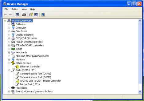
CP210x before Driver Installation – WinXP
- Next, right click on ‘CP2102 USB to UART Bridge Controller’ and click on ‘Update Driver’.
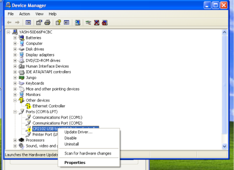
CP210x before Driver Update Step – WinXP
- Next you’ll see this window.
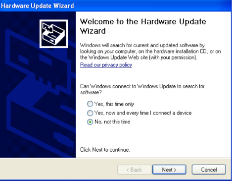
Hardware Update Wizard – WinXP
- Select ‘No, Not this time’ and press Next.
- In the next window, select ‘Install from a specific location’ and press Next.
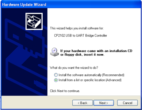
Hardware Update Wizard Install Location – WinXP
- In this window, chose the location of your Drivers, and then press Next. If there is check box saying “Include sub-folders”, then make sure it is checked.
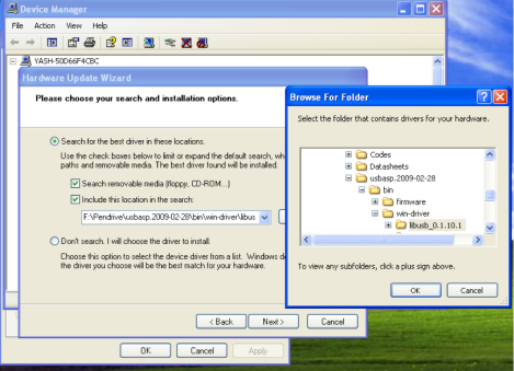
Hardware Update Wizard Browse – WinXP
- And it’s done! 😀
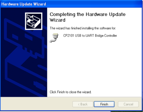
Hardware Update Wizard Finish – WinXP
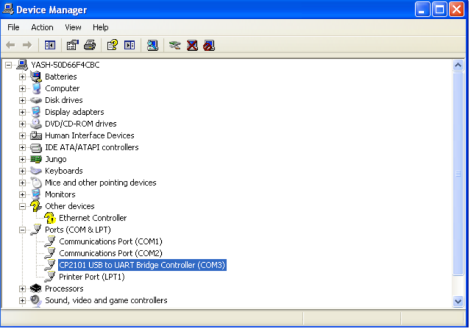
CP210x after Driver Installation – WinXP


Once the driver is installed, your device will be assigned a COM port (COM3 in this case). Note that driver installation needs to be done only once. Once installed, whenever you connect your device in future, your computer will recognize it automatically and assign a COM port number to the device. You can know the COM port number from the Device Manager. This COM port number is essential for a successful serial communication, as we will see later.
Connecting CP210x to Mac OS X
Connecting the USB-UART Bridge and installing its drivers in a MAC is much easier as compared to Windows. Simply follow the steps below:
- Connect your Bridge to your MAC.
- You will see the red light on your bridge glowing.
- Just open the drivers you have downloaded and double click on them to install them. You will see an install pane like this:
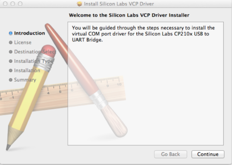
CP210x Driver Installation – Mac
- Click on Continue, and keep clicking on continue, and in the end you’ll see the installation is complete! Cheers! 🙂

Using RealTerm on PC
RealTerm is a free software that is used for serial communication through your PC. It can be downloaded from here.
Step 1
Open RealTerm. You will see a window like this pop up.

RealTerm Initial Window
This is the main window of RealTerm. You can see various options here. Right now, we are only concerned with ‘Display’ and ‘Port’. On the right you can see ‘Status’ Menu. This indicates the status of your UART Device.
Then Connect your USB-UART Bridge to your PC.
Step 2
Go to the PORT option. Here you can set the Baud rate, number of stop bits, parity, Number of data bits and PORT.
Set the baud rate whatever you like, but don’t select too high baud rates, because higher baud rates sometimes cause errors. Select at max 115200. Choose your COM port (in this case, choose 3 since your device is connected to COM3 port).

RealTerm Port Settings
It is the PORT option with which we are concerned. Here you have to set the COM Port Number on which you have connected your Bridge module. To know on which port you have connected it, go to My Computer → Properties → Device Manager → USB Devices → CP210x Module. Then enter the ‘x’ from the COMx in the PORT.
Choose the following settings:
- Baud: 9600 (max 115200)
- Port: 3 (or whatever is your COM port value)
- Parity: None
- Data Bits: 8 bits
- Stop Bits: 1 bit
- Hardware Flow Control: None
Then click on Open.
When you do this, the block corresponding to ‘Connected’ in the Status menu should turn to Green. If it doesn’t, then quit RealTerm, disconnect and reconnect your device and start RealTerm again.
NOTE: This problem occurs quite frequently, and you might have to repeat this procedure a couple of times before your device actually connects to RealTerm.
Step 3
Once your device is connected, then whenever you press any key on your keyboard (except direction keys, and the ones whose ASCII values are not defined), you will see that the TXD, as well as RXD in the Status get lit up. Also, you’ll see that whatever you type appears on the black console area.
NOTE: Whatever you type using is keyboard is actually transmitted from your PC. You cannot see what is transmitted. You see only the characters you have received. In this case, the characters sent by the PC are received by the PC itself (loopback), and hence you see the exact same thing! In our upcoming posts, we will see how this data can be modified by a microcontroller, and you will see a different data as compared to what you type.
That’s it, you’re done! 🙂
Using CoolTerm on Mac
CoolTerm is another serial terminal emulator available for Unix platforms. It is a very simple to use terminal emulator, though has a drawback when compared to RealTerm, that while RealTerm can be used for almost all serial communication protocols, wiz. UART, SPI and I2C, CoolTerm can only be used for UART.
Step1
Open CoolTerm. The GUI is very simple and User Friendly, thanks to Roger Meier! 🙂

CoolTerm Initial Window
Step 2
Click on OPTIONS.

CoolTerm Options
In the PORT option, select ‘SLAB_USBtoUART’ as shown. Set the desired baud rate and other parameters. Let’s choose the same settings as we did for RealTerm previously.
- Port: SLAB_USBtoUART
- Baud: 9600 (max 115200)
- Parity: None
- Data Bits: 8 bits
- Stop Bits: 1 bit
- Hardware Flow Control: None
Click on OK.
Step 3
After you click OK, you will then again see the default window. On the top, you’ll find ‘Connect’ button. Click on it.

CoolTerm Connected
After pressing the CONNECT button, you will see some of the green Lights on the bottom right corner have lit up. Also, on the bottom left corner, you can see the device name (SLAB_USBtoUART), Baud (9600), Number of Data bits (8), Polarity (N) and number of stop Bits (1).
And Most importantly, you will see ‘Connected’, which means the Terminal Emulator app is now communicating with your USB_UART Bridge! 😀
Step 4
Now since we are executing a loopback test, we will receive whatever we are sending through the terminal. I send the following, and received it back!

CoolTerm Loopback Example
If it does, your loopback test is complete! 🙂 Cheers! 😀 I would like to put the same note here as well, just in case Mac users have skipped the previous step.
NOTE: Whatever you type using is keyboard is actually transmitted from your PC. You cannot see what is transmitted. You see only the characters you have received. In this case, the characters sent by the PC are received by the PC itself (loopback), and hence you see the exact same thing! In our upcoming posts, we will see how this data can be modified by a microcontroller, and you will see a different data as compared to what you type.
Video
Now time for some videos! In the following video, you can see how to use RealTerm on a PC and CoolTerm on a Mac. Device Manager is also shown in the video. We hope you enjoy and learn from the video and apologize for the background noise! 😉
Summary
Lets summarize what we learnt in this post:
- RS232 is one of the most commonly used serial protocols. It can be operated via the DB9 port, DB25 port or the USB port as well.
- There are several logic level families, and we are concerned with TTL and RS-232.
- We need to convert the logic level in between TTL and RS-232 for a successful communication, which can be done using Zener diode, IC MAX232 and IC CP210x.
- Simplest way to check for RS232 communication is the loopback test where the data transmitted from the PC is fed back to the receiver terminal of PC.
- The driver for CP210x can be installed on all platforms – Windows, Mac and Linux.
- A serial terminal can be used to establish a communication between a PC/Mac and other devices.
- One such serial terminal for Windows is RealTerm and for Mac is CoolTerm.
So this is the end of another long, and hopefully interesting post! We await your responses and queries, which you can type in down below! In the next post, we will deal with AVR microcontrollers, and learn how to send and receive data using its USART. Till then, enjoy and subscribe to stay updated! 🙂
Written By-
Yash Tambi
VIT University, Vellore
tambi@maxEmbedded.com
QC and Mentorship By-
Mayank Prasad
Arizona State University
max@maxEmbedded.com

well explained, i would advise for the next tutorial to explain how to calibrate a uController when sending data without a crystal on the board, inter board UART, inter board 232 as well as uController to PC echo program.
but highly important would be interrupt driven UART with the pc, I would be mostly curious for a simple sockets program on C++ perhaps using dev C++ console app or something simple to control a micro from PC
Hi Ovi,
Thanks for the suggestion. I guess the first concern has already been taken care of. Regarding interrupt driven UART, we will deal with AVR interrupts in general and learn how to use them for UART operation, trigger ADC, start/stop timer, etc. But that will be after we are done with the I2C post.
Pingback: The USART of the AVR | maxEmbedded·
sir,
max232 converts RS232 TO TTL
cp2102 converts usb to uart
i want to know that which protocol we need on uc side(TTL OR UART)??
What is logic levels for UART and USB??
Hello Pradeep,
On the microcontroller side, you need to have UART (or RS232) logic level. Logic level of UART/RS232 is already stated in the article, please go through it. TTL comes in between USB and UART levels. Does it make sense?
Pingback: Serial Peripheral Interface – SPI Basics | maxEmbedded·
Zener diode on picture is placed wrong.
Pingback: The SPI of the AVR | maxEmbedded·
zener diode is forword bias, i think it must be in reverse bias. 🙂
Yes it has to be reverse biased! 🙂
Nice post but either I am misunderstanding your DB25 explanation or you haven’t done your homework on the parallel (printer) port. The DB25 connector was, for a time, used for both serial and parallel data transfer on the IBM PC (See http://en.wikipedia.org/wiki/Parallel_port). Don’t confuse the connector hardware with communication protocol using that connector.
Another point where I think you are misleading is when you say that because the communication takes place through two channels it is a parallel port for RS232. Serial output and parallel output are quite different I/O mechanisms. As can be seen in the quoted Wikipedia article parallel communication inputs or outputs 8, or more, bits of data at a time and serial communication inputs or outputs 1 bit of data at a time.
Hello Thomas,
Sorry for the delayed response. I do accept the fact that the things that you pointed out were wrongly represented in the tutorial. I made the necessary edits based on your points. Thank you so much, I really appreciate that.
Best, Max
Hello Mayank,
Currently, I am dealing with ATmeg8 using crystal 11.0592MHz and its ADC0. I am using serial port to communicate with it. For my application, I do need high baud rate (nearly 115200BR). But, I am able to get till 38400. Beyond that I am getting garbage data. I’ve tried hyperTerminal , terminal .
Is there any way to get it??
Hello Amit,
May I know how did you determine that 38400 bps is the maximum baud rate you can achieve using ATmega8?
Hello Mayank,
Sorry for late reply.
I’ve tried higher than 38400, but it is not working for me. 😦
Anything I missed??
As per my calculations, baud rate of 38400 is possible. Can you show me the way you calculated.
Pingback: Inter-Integrated Circuit – I2C Basics | maxEmbedded·
I wanted to communicate between a Mac and a windows pc. I used the same tools but even get a mess. I can transmit something but everything is shown wrong
Hey Schlonz,
Are you using a USB-UART bridge? And I assume that you have connected them together using wires (i.e. it is NOT wireless). Cuz if that is the case, then there should not be any issues. Make sure that you have the same settings for the terminal software in both PC and Mac. Let me know if you have any trouble.