

Dear readers, please note that this is the old website of maxEmbedded. The articles are now no longer supported, updated and maintained. Please visit the new website here and search for this post. Alternatively, you can remove .wordpress from the address bar to reach the new location.
Example: If the website address is http://maxEmbedded.wordpress.com/contact/, then removing .wordpress from it will become http://maxEmbedded.com/contact/.
We apologize for the inconvenience. We just want to give you a better viewing and learning experience! Thanks!
Hey folks! Lets continue with our tutorials on Serial Communication. Until now, we have seen a general introduction to serial communication, followed by a tutorial on the concepts of RS-232 communication. So here we are with the AVR communication protocols series, starting with the most basic ones, UART and USART! We will move on to SPI and TWI (I2C) later.
Some images used in this tutorial are taken directly from (and are a courtesy of) the AVR datasheets for ATMega8 and ATMega16/32 microcontrollers.
Contents
UART and USART
The UART and USART have already been discussed here. Anyways, lets have a quick recap.
UART stands for Universal Asynchronous Receiver/Transmitter. From the name itself, it is clear that it is asynchronous i.e. the data bits are not synchronized with the clock pulses.
USART stands for Universal Synchronous Asynchronous Receiver/Transmitter. This is of the synchronous type, i.e. the data bits are synchronized with the clock pulses.
If you refer to the USART section in the datasheet of any AVR microcontroller, you will find several features listed there. Some of the main features of the AVR USART are:
- Full Duplex Operation (Independent Serial Receive and Transmit Registers)
- Asynchronous or Synchronous Operation
- Master or Slave Clocked Synchronous Operation
- High Resolution Baud Rate Generator
- Supports Serial Frames with 5, 6, 7, 8, or 9 Data bits and 1 or 2 Stop Bits
USART Layout – How to set it up?
Before we continue, please note that the AVR USART is fully compatible with the AVR UART in terms of register bit locations, baud rate generation, transmitter/receiver operations and buffer functionality. So let us now have a quick look at how to set up USART in general. We will discuss in detail later.
- The first step is to set the baud rate in both, the master and the slave. The baud rate has to be the same for both – master and slave.
- Set the number of data bits, which needs to be sent.
- Get the buffer ready! In case of transmission (from AVR to some other device), load it up with the data to be sent, whereas in case of reception, save the previous data so that the new received data can be overwritten onto it.
- Then enable the transmitter/receiver according to the desired usage.
One thing to be noted is that in UART, there is no master or slave since master is defined by the MicroController, which is responsible for clock pulse generation. Hence Master and Slave terms occur only in the case of USART.
Master µC is the one which is responsible for Clock pulse generation on the Bus.
USART Pin Configuration
Now lets have a look at the hardware pins related to USART. The USART of the AVR occupies three hardware pins pins:
- RxD: USART Receiver Pin (ATMega8 Pin 2; ATMega16/32 Pin 14)
- TxD: USART Transmit Pin (ATMega8 Pin 3; ATMega16/32 Pin 15)
- XCK: USART Clock Pin (ATMega8 Pin 6; ATMega16/32 Pin 1)
Modes of Operation
The USART of the AVR can be operated in three modes, namely-
- Asynchronous Normal Mode
- Asynchronous Double Speed Mode
- Synchronous Mode
Asynchronous Normal Mode
In this mode of communication, the data is transmitted/received asynchronously, i.e. we do not need (and use) the clock pulses, as well as the XCK pin. The data is transferred at the BAUD rate we set in the UBBR register. This is similar to the UART operation.
Asynchronous Double Speed Mode
This is higher speed mode for asynchronous communication. In this mode also we set the baud rates and other initializations similar to Normal Mode. The difference is that data is transferred at double the baud we set in the UBBR Register.
Setting the U2X bit in UCSRA register can double the transfer rate. Setting this bit has effect only for the asynchronous operation. Set this bit to zero when using synchronous operation. Setting this bit will reduce the divisor of the baud rate divider from 16 to 8, effectively doubling the transfer rate for asynchronous communication. Note however that the Receiver will in this case only use half the number of samples (reduced from 16 to 8) for data sampling and clock recovery, and therefore a more accurate baud rate setting and system clock are required when this mode is used. For the Transmitter, there are no downsides.
Synchronous Mode
This is the USART operation of AVR. When Synchronous Mode is used (UMSEL = 1 in UCSRC register), the XCK pin will be used as either clock input (Slave) or clock output (Master).
Baud Rate Generation
The baud rate of UART/USART is set using the 16-bit wide UBRR register. The register is as follows:

UBRR Register (Click to Enlarge)
Since AVR is an 8-bit microcontroller, every register should have a size of 8 bits. Hence, in this case, the 16-bit UBRR register is comprised of two 8-bit registers – UBRRH (high) and UBRRL (low). This is similar to the 16-bit ADC register (ADCH and ADCL, remember?). Since there can be only specific baud rate values, there can be specific values for UBRR, which when converted to binary will not exceed 12 bits. Hence there are only 12 bits reserved for UBRR[11:0]. We will learn how to calculate the value of UBRR in a short while in this post.
The USART Baud Rate Register (UBRR) and the down-counter connected to it functions as a programmable prescaler or baud rate generator. The down-counter, running at system clock (FOSC), is loaded with the UBRR value each time the counter has counted down to zero or when the UBRRL Register is written. A clock is generated each time the counter reaches zero.
This clock is the baud rate generator clock output (= FOSC/(UBRR+1)). The transmitter divides the baud rate generator clock output by 2, 8, or 16 depending on mode. The baud rate generator output is used directly by the receiver’s clock and data recovery units.
Below are the equations for calculating baud rate and UBRR value:

Baud Rate Calculation (Click to Enlarge)
- BAUD = Baud Rate in Bits/Second (bps) (Always remember, Bps = Bytes/Second, whereas bps = Bits/Second)
- FOSC = System Clock Frequency (1MHz) (or as per use in case of external oscillator)
- UBRR = Contents of UBRRL and UBRRH registers
Frame Formats
A frame refers to the entire data packet which is being sent/received during a communication. Depending upon the communication protocol, the formats of the frame might vary. For example, TCP/IP has a particular frame format, whereas UDP has another frame format. Similarly in our case, RS232 has a typical frame format as well. If you have gone through the loopback test discussed in the previous tutorial, you will notice that we have chosen options such as 8 bits data, 1 stop bit, no parity, etc. This is nothing but the selection of a frame format!
A typical frame for USART/RS232 is usually 10 bits long: 1 start bit, 8 data bits, and a stop bit. However a vast number of configurations are available… 30 to be precise!

Frame Format (Click to Enlarge)
Order of Bits
- Start bit (Always low)
- Data bits (LSB to MSB) (5-9 bits)
- Parity bit (optional) (Can be odd or even)
- Stop bit (1 or 2) (Always high)
A frame starts with the start bit followed by the least significant data bit. Then the next data bits, up to a total of nine, are succeeding, ending with the most significant bit. If enabled, the parity bit is inserted after the data bits, before the stop bits. When a complete frame is transmitted, a new frame can directly follow it, or the communication line can be set to an idle (high) state. Here is the frame format as mentioned in the AVR datasheet-

Frame Format (Click to Enlarge)
Note: The previous image (not the above one, the one before that) of Frame Format has a flaw in it! If you can find it, feel free to comment below! Let me see how many of you can spot it! And I’m not kidding, there is a mistake! 😉
Setting the Number of DATA Bits
The data size used by the USART is set by the UCSZ2:0, bits in UCSRC Register. The Receiver and Transmitter use the same setting.
Note: Changing the settings of any of these bits (on the fly) will corrupt all ongoing communication for both the Receiver and Transmitter. Make sure that you configure the same settings for both transmitter and receiver.

Data Bit Settings (Click to Enlarge)
Setting Number of STOP Bits
This bit selects the number of stop bits to be inserted by the transmitter. The Receiver ignores this setting. The USBS bit is available in the UCSRC Register.

Stop Bit Settings (Click to Enlarge)
Parity Bits
Parity bits always seem to be a confusing part. Parity bits are the simplest methods of error detection. Parity is simply the number of ‘1’ appearing in the binary form of a number. For example, ‘55’ in decimal is 0b00110111, so the parity is 5, which is odd.
Even and Odd Parity
In the above example, we saw that the number has an odd parity. In case of even parity, the parity bit is set to 1, if the number of ones in a given set of bits (not including the parity bit) is odd, making the number of ones in the entire set of bits (including the parity bit) even. If the number of ones in a given set of bits is already even, it is set to a 0. When using odd parity, the parity bit is set to 1 if the number of ones in a given set of bits (not including the parity bit) is even, making the number of ones in the entire set of bits (including the parity bit) odd. When the number of set bits is odd, then the odd parity bit is set to 0.
Still confused? Simply remember – even parity results in even number of 1s, whereas odd parity results in odd number of 1s. Lets take another example. 0d167 = 0b10100111. This has five 1s in it. So in case of even parity, we add another 1 to it to make the count rise to six (which is even). In case of odd parity, we simply add a 0 which will stall the count to five (which is odd). This extra bit added is called the parity bit! Check out the following example as well (taken from Wikipedia):
|
7 bits of data |
(count of 1 bits) | 8 bits including parity | |
|---|---|---|---|
| even |
odd |
||
| 0000000 | 0 | 00000000 | 00000001 |
| 1010001 | 3 | 10100011 | 10100010 |
| 1101001 | 4 | 11010010 | 11010011 |
| 1111111 | 7 | 11111111 | 11111110 |
But why use the Parity Bit?
Parity bit is used to detect errors. Lets say we are transmitting 0d167, i.e. 0b10100111. Assuming an even parity bit is added to it, the data being sent becomes 0b101001111 (pink bit is the parity bit). This set of data (9 bits) is being sent wirelessly. Lets assume in the course of transmission, the data gets corrupted, and one of the bits is changed. Ultimately, say, the receiver receives 0b100001111. The blue bit is the error bit and the pink bit is the parity bit. We know that the data is sent according to even parity. Counting the number of 1s in the received data, we get four (excluding even parity bit) and five (including even parity bit). Now doesn’t it sound amusing? There should be even number of 1s including the parity bit, right? This makes the receiver realize that the data is corrupted and will eventually discard the data and wait/request for a new frame to be sent. This is explained in the following diagram as well-

Why do we need Parity Bit? (Click to Enlarge)
Limitations of using single parity bit is that it can detect only single bit errors. If two bits are changed simultaneously, it fails. Using Hamming Code is a better solution, but it doesn’t fit in for USART and is out of the scope of this tutorial as well!
The Parity Generator calculates the parity bit for the serial frame data. When parity bit is enabled (UPM1 = 1), the Transmitter control logic inserts the parity bit between the last data bit and the first stop bit of the frame that is sent. The parity setting bits are available in the UPM1:0 bits in the UCSRC Register.

Parity Settings (Click to Enlarge)
Although most of the times, we do not require parity bits.
Register Description
Now lets learn about the registers which deal with the USART. If you have worked with ADC and timers before, you would know that we need to program the registers in order to make the peripheral work. The same is the case with USART. The USART of AVR has five registers, namely UDR, UCSRA, UCSRB, UCSRC and UBBR. We have already discussed about UBBR earlier in this post, but we will have another look.
UDR: USART Data Register (16-bit)

UDR – UART Data Register (Click to Enlarge)
The USART Transmit Data Buffer Register and USART Receive Data Buffer Registers share the same I/O address referred to as USART Data Register or UDR. The Transmit Data Buffer Register (TXB) will be the destination for data written to the UDR Register location. Reading the UDR Register location will return the contents of the Receive Data Buffer Register (RXB).
For 5-, 6-, or 7-bit characters the upper unused bits will be ignored by the Transmitter and set to zero by the Receiver.
UCSRA: USART Control and Status Register A (8-bit)

UCSRA – USART Control and Status Register A (Click to Enlarge)
- Bit 7: RxC – USART Receive Complete Flag: This flag bit is set by the CPU when there are unread data in the Receive buffer and is cleared by the CPU when the receive buffer is empty. This can also be used to generate a Receive Complete Interrupt (see description of the RXCIE bit in UCSRB register).
- Bit 6: TxC – USART Transmit Complete Flag: This flag bit is set by the CPU when the entire frame in the Transmit Shift Register has been shifted out and there is no new data currently present in the transmit buffer (UDR). The TXC Flag bit is automatically cleared when a Transmit Complete Interrupt is executed, or it can be cleared by writing a one (yes, one and NOT zero) to its bit location. The TXC Flag can generate a Transmit Complete Interrupt (see description of the TXCIE bit in UCSRB register).
- Bit 5: UDRE – USART Data Register Empty: The UDRE Flag indicates if the transmit buffer (UDR) is ready to receive new data. If UDRE is one, the buffer is empty, and therefore ready to be written. The UDRE Flag can generate a Data Register Empty Interrupt (see description of the UDRIE bit in UCSRB register). UDRE is set after a reset to indicate that the Transmitter is ready.
- Bit 4: FE – Frame Error: This bit is set if the next character in the receive buffer had a Frame Error when received (i.e. when the first stop bit of the next character in the receive buffer is zero). This bit is valid until the receive buffer (UDR) is read. The FE bit is zero when the stop bit of received data is one. Always set this bit to zero when writing to UCSRA.
- Bit 3: DOR – Data Overrun Error: This bit is set if a Data OverRun condition is detected. A Data OverRun occurs when the receive buffer is full (two characters), and a new start bit is detected. This bit is valid until the receive buffer (UDR) is read. Always set this bit to zero when writing to UCSRA.
- Bit 2: PE – Parity Error: This bit is set if the next character in the receive buffer had a Parity Error when received and the parity checking was enabled at that point (UPM1 = 1). This bit is valid until the receive buffer (UDR) is read. Always set this bit to zero when writing to UCSRA.
- Bit 1: U2X – Double Transmission Speed: This bit only has effect for the asynchronous operation. Write this bit to zero when using synchronous operation. Writing this bit to one will reduce the divisor of the baud rate divider from 16 to 8 effectively doubling the transfer rate for asynchronous communication.
- Bit 0: MPCM – Multi-Processor Communication Mode: This bit enables the Multi-processor Communication mode. When the MPCM bit is written to one, all the incoming frames received by the USART Receiver that do not contain address information will be ignored. The Transmitter is unaffected by the MPCM setting. This is essential when the receiver is exposed to more than one transmitter, and hence must use the address information to extract the correct information.
UCSRB: USART Control and Status Register B (8-bit)

UCSRB – USART Control and Status Register B (Click to Enlarge)
- Bit 7: RXCIE – RX Complete Interrupt Enable: Writing this bit to one enables interrupt on the RXC Flag. A USART Receive Complete interrupt will be generated only if the RXCIE bit is written to one, the Global Interrupt Flag in SREG is written to one and the RXC bit in UCSRA is set. The result is that whenever any data is received, an interrupt will be fired by the CPU.
- Bit 6: TXCIE – TX Complete Interrupt Enable: Writing this bit to one enables interrupt on the TXC Flag. A USART Transmit Complete interrupt will be generated only if the TXCIE bit is written to one, the Global Interrupt Flag in SREG is written to one and the TXC bit in UCSRA is set. The result is that whenever any data is sent, an interrupt will be fired by the CPU.
- Bit 5: UDRIE – USART Data Register Empty Interrupt Enable: Writing this bit to one enables interrupt on the UDRE Flag (remember – bit 5 in UCSRA?). A Data Register Empty interrupt will be generated only if the UDRIE bit is written to one, the Global Interrupt Flag in SREG is written to one and the UDRE bit in UCSRA is set. The result is that whenever the transmit buffer is empty, an interrupt will be fired by the CPU.
- Bit 4: RXEN – Receiver Enable: Writing this bit to one enables the USART Receiver. The Receiver will override normal port operation for the RxD pin when enabled.
- Bit 3: TXEN – Transmitter Enable: Writing this bit to one enables the USART Transmitter. The Transmitter will override normal port operation for the TxD pin when enabled.
- Bit 2: UCSZ2 – Character Size: The UCSZ2 bits combined with the UCSZ1:0 bits in UCSRC register sets the number of data bits (Character Size) in a frame the Receiver and Transmitter use. More information given along with UCSZ1:0 bits in UCSRC register.
- Bit 1: RXB8 – Receive Data Bit 8: RXB8 is the ninth data bit of the received character when operating with serial frames with nine data bits. It must be read before reading the low bits from UDR.
- Bit 0: TXB8 – Transmit Data Bit 8: TXB8 is the ninth data bit in the character to be transmitted when operating with serial frames with nine data bits. It must be written before writing the low bits to UDR.
UCSRC: USART Control and Status Register C (8-bit)
The UCSRC register can be used as either UCSRC, or as UBRRH register. This is done using the URSEL bit.

UCSRC – USART Control Register C (Click to Enlarge)
- Bit 7: URSEL – USART Register Select: This bit selects between accessing the UCSRC or the UBRRH Register. It is read as one when reading UCSRC. The URSEL must be one when writing the UCSRC.
- Bit 6: UMSEL – USART Mode Select: This bit selects between Asynchronous and Synchronous mode of operation.
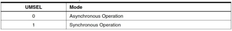
Synchronous/Asynchronous Selection (Click to Enlarge)

- Bit 5:4: UPM1:0 – Parity Mode: This bit helps you enable/disable/choose the type of parity.
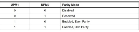
Parity Settings (Click to Enlarge)

- Bit 3: USBS – Stop Bit Select: This bit helps you choose the number of stop bits for your frame.
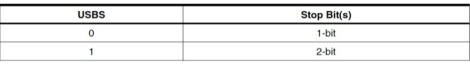
Stop Bit Settings (Click to Enlarge)

- Bit 2:1: UCSZ1:0 – Character Size: These two bits in combination with the UCSZ2 bit in UCSRB register helps choosing the number of data bits in your frame.
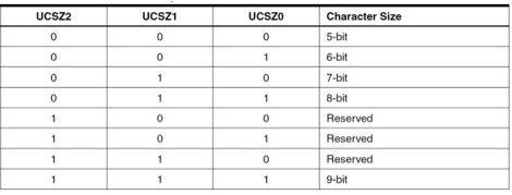
Data Bit Settings (Click to Enlarge)

- Bit 0: UCPOL – Clock Polarity: This bit is used for Synchronous mode only. Write this bit to zero when Asynchronous mode is used. The UCPOL bit sets the relationship between data output change and data input sample, and the synchronous clock (XCK).
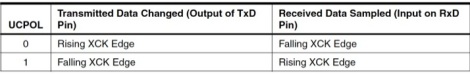
UCPOL Bit Settings (Click to Enlarge)

UBRR: USART Baud Rate Register (16-bit)
UBRR Register (Click to Enlarge)
We have already seen this register, except the URSEL bit.
- Bit 15: URSEL: This bit selects between accessing the UBRRH or the UCSRC Register. It is read as zero when reading UBRRH. The URSEL must be zero when writing the UBRRH.
Let’s code it!
Now its been enough of theory. Let’s get our hands dirty with some actual code! Here is how we will structure out code – first initialize UART, then read from it, and then write to it.
Initializing UART
Initializing UART involves the following steps:
- Setting the Baud Rate
- Setting Data Size (5/6/7/8/9 bits)
- Enabling Reception/ Transmission (In the TXEN and RXEN bits in UCSRB)
- Setting parity, and number of Stop Bits.
Below is the code to initialize UART, explanation follows it. You can scroll the code sideways in order to view it completely.
// define some macros
#define BAUD 9600                                   // define baud
#define BAUDRATE ((F_CPU)/(BAUD*16UL)-1)            // set baud rate value for UBRR

// function to initialize UART
void uart_init (void)
{
	UBRRH = (BAUDRATE>>8);                      // shift the register right by 8 bits
	UBRRL = BAUDRATE;                           // set baud rate
	UCSRB|= (1<<TXEN)|(1<<RXEN);                // enable receiver and transmitter
	UCSRC|= (1<<URSEL)|(1<<UCSZ0)|(1<<UCSZ1);   // 8bit data format
}
Explanation
The variable (or macro) used to set the baud rate is BAUD. The variable (or macro) BAUDRATE is defined as per the calculations according to which, the baud rate is set in the registers.
One thing to note is that UCSRC and UBRRH share the same I/O location in the memory. So, the bit that controls the selection/switching of the registers is the URSEL Bit in the UCSRC register. This creates a lot of confusion, and if this bit is not handled properly, UART doesn’t work! So pay attention to the code initialization.
If URSEL is zero during a write operation, the UBRRH value will be updated. If URSEL is one, the UCSRC setting will be updated. This means that while URSEL bit is 0, and even if we are addressing UCSRC, UBBRH will be addressed, which would in turn result in setting up of wrong, non standard baud rates, and everything getting messed up! Since the default value of URSEL is 0, it is safe to first use UBRRH, and then use the UCSRC Register.
The bits TxEN and RxEN are set to 1 to enable UART transmission and reception.
The Bits UCSZ0 and UCSZ1 are used to select the number of data bits to be transmitted. As per the table, we have set the two bits to transmit/receive 8 bits.
Transmission/Reception Code
The following code is for transmitting data, explanation follows it. You can scroll the code sideways in order to view to code completely.
// function to send data
void uart_transmit (unsigned char data)
{
	while (!( UCSRA & (1<<UDRE)));                // wait while register is free
	UDR = data;                                   // load data in the register
}
The following code is for transmitting data, explanation follows it. You can scroll the code sideways in order to view to code completely.
// function to receive data
unsigned char uart_recieve (void)
{
	while(!(UCSRA) & (1<<RXC));                   // wait while data is being received
	return UDR;                                   // return 8-bit data
}
Explanation
The above code snippets are to transmit and receive data respectively. In both of them, we first wait for the flag bits denoting data register empty bit UDRE, and receive complete RXC bit respectively to get set, and then take the next action.
When we transmit the data, we load the 8-bit data into the UDR (UART Data Register) to be transmitted.
When we want to receive data, we wait for the whole data to be received first, and then return the value of the received data stored in UDR.
Problem Statement
Let’s take a problem statement now. Let’s say we have to send serial data through a serial terminal emulator on a PC, and receive it on a AVR microcontroller, and display it on an LCD. The displayed values should be in ASCII format.
Methodology
For this, we need to connect an LCD to our microcontroller, and configure the LCD header file accordingly. To learn about interfacing LCD with AVR, read this tutorial written by Mayank. We will also need to connect the USB-UART Bridge with the microcontroller. If you have followed the loopback test of the previous tutorial, then this will be easy for you. Here is the methodology you need to follow:
- Send data from your PC using a serial terminal emulator. This has been discussed in the loopback test.
- Connect your microcontroller to your PC using the USB-UART Bridge. Schematics follow.
- Connect your LCD with your microcontroller. Schematics follow.
- Receive serial data through the RxD pin of your microcontroller.
- Process the data.
- Display the data in the LCD.
Hardware Connections
Here is the schematics which shows how to connect LCD and USB-UART Bridge with your microcontroller. Remember, the TX of USB-UART bridge is connected to the RX of the microcontroller, and vice versa.

UART-LCD Schematics (Click to Enlarge)
Coding
I have made some changes in the LCD header file (lcd.h), so that the LCD is operated by 2 ports (PORTB and PORTD) instead of a single port. Following are the changes: (refer to this tutorial to know more)
#define LCD_PORT1        PORTD         /**< port1 for the LCD lines  */
#define LCD_PORT2        PORTB         /**< port2 for the LCD lines  */
#define LCD_DATA0_PORT   LCD_PORT2     /**< port for 4bit data bit 0 */
#define LCD_DATA1_PORT   LCD_PORT2     /**< port for 4bit data bit 1 */
#define LCD_DATA2_PORT   LCD_PORT2     /**< port for 4bit data bit 2 */
#define LCD_DATA3_PORT   LCD_PORT2     /**< port for 4bit data bit 3 */
#define LCD_DATA0_PIN    0             /**< pin for 4bit data bit 0  */
#define LCD_DATA1_PIN    1             /**< pin for 4bit data bit 1  */
#define LCD_DATA2_PIN    2             /**< pin for 4bit data bit 2  */
#define LCD_DATA3_PIN    3             /**< pin for 4bit data bit 3  */
#define LCD_RS_PORT      LCD_PORT1     /**< port for RS line         */
#define LCD_RS_PIN       5             /**< pin  for RS line         */
#define LCD_RW_PORT      LCD_PORT1     /**< port for RW line         */
#define LCD_RW_PIN       6             /**< pin  for RW line         */
#define LCD_E_PORT       LCD_PORT1     /**< port for Enable line     */
#define LCD_E_PIN        7             /**< pin  for Enable line     */
What I am going to demonstrate here is very simple. We just need to configure LCD, UART, and its done! Below is the full code. The code is commented well, and doesn’t need any further explanation (provided you have understood all the concepts till now, which I truly believe!). In case you need any help in comprehending the code, feel free to comment below. You can scroll the code sideways in order to view to code completely.
Full Code
You can also find the code on pastebin, and the AVR code gallery. The AVR code gallery contains the LCD files as well. To learn how to write, build, compile and execute your code using Atmel Studio 6, view this tutorial.
#include <avr/io.h>
#include <util/delay.h>
#include <stdlib.h>
#include "lcd.h"							// include LCD library

#define BAUD 9600							// define baud
#define BAUDRATE ((F_CPU)/(BAUD*16UL)-1)	// set baudrate value for UBRR

#ifndef F_CPU
#define F_CPU 16000000UL					// set the CPU clock
#endif

// function to initialize UART
void uart_init (void)
{
	UBRRH=(BAUDRATE>>8);
	UBRRL=BAUDRATE;							//set baud rate
	UCSRB|=(1<<TXEN)|(1<<RXEN); 			//enable receiver and transmitter
	UCSRC|=(1<<URSEL)|(1<<UCSZ0)|(1<<UCSZ1);// 8bit data format
}

// function to send data - NOT REQUIRED FOR THIS PROGRAM IMPLEMENTATION
void uart_transmit (unsigned char data)
{
	while (!( UCSRA & (1<<UDRE))); 			// wait while register is free
	UDR = data; 							// load data in the register
}

// function to receive data
unsigned char uart_recieve (void)
{
	while(!(UCSRA) & (1<<RXC)); 			// wait while data is being received
	return UDR; 							// return 8-bit data
}

// main function: entry point of program
int main (void)
{
	unsigned char a;
	char buffer[10];

	uart_init(); 							// initialize UART
	lcd_init(LCD_DISP_ON_CURSOR); 			// initialize LCD
	lcd_home(); 							// goto LCD Home

  	while(1)
  	{
		a=uart_recieve(); 					// save the received data in a variable
		itoa(a,buffer,10); 					// convert numerals into string
		lcd_clrscr(); 						// LCD clear screen
		lcd_home();							// goto LCD home
		lcd_puts(buffer); 					// display the received value on LCD
		_delay_ms(100);						// wait before next attempt
  	}

  	return 0;
}
Hardware Setup
My hardware setup looked something like this–

AVR USART Hardware Setup (Click to Enlarge)
Video
Here is a short video of the implementation of the above code.
Can you do it?
Alright, so this was just an introduction. You can try out the following things as well by modifying the above code:
- Extend the above problem statement by sending back the data you received from the computer with some alterations. For example, if you send
maxEmbeddedfrom your PC, you should receive[m][a][x][E][m][b][e][d][d][e][d]back from the microcontroller, which should be displayed in the serial terminal console window.
Hint: While sending the received data, send it in between[and].a. Receive Data b. Send '[' c. Send received Data back d. Send ']' e. Repeat this forever
- Send data from one microcontroller to another microcontroller, and display the result using an LCD.
Hint: You should connect the TXD of one microcontroller to RXD of another microcontroller. You can use wired connection for now. - Extend the above to a full-duplex communication. Two microcontrollers send and receive data simultaneously.
Hint: Connect TXD of one microcontroller to RXD of other. You can use wired connection for now.
Do it and show the world that you are awesome!
If you have tried any of the above three challenges, then you are most welcome to record a video of your implementation, post it on YouTube and share the link below as comment! This will ensure that the world looks at your awesomeness. But wait, its not over yet! Your video might get featured just below this line as well! So, what are you waiting for?
Summary
Now that we have come to an end of another long post, let’s summarize what we have learnt–
- We know what’s UART and USART.
- We know how to set up USART, its pin configuration and three modes of operation.
- We learnt how to set baud rate for a USART data transfer.
- We learnt how to send the data – frame formats, data bits, stop bits, and about parity.
- We got familiarized with different USART registers – UDR, UCSRA, UCSRB, UCSRC and UBRR.
- We saw some sample codes, and then implemented a problem statement as well.
- We learnt how to make hardware connections as well.
So folks, that’s it for now. We will return back soon with more tutorials! 🙂 So subscribe to stay updated! And don’t forget to share your views and questions as comments below! 🙂
Written By-
Yash Tambi
VIT University, Vellore
tambi@maxEmbedded.com
Mayank Prasad
Arizona State University
max@maxEmbedded.com

Hello Yash, I need some help,about two matters below: 1.I am interesting to write GUI program for embedded system like platform for CNC routers robot controller etc. so please inform me in which language will best for precise like motor driver gantry c++ or java or another. 2. I need relay but I don’t know how I can write code in C if u can give an example piece of code. Thanks,Rose
On Mon, Oct 21, 2013 at 10:04 AM, maxEmbedded
Hello Rose!
1. Currently we have a very limited knowledge about GUI, but as far as we know, PHP would be the simplest.
2. By relay, do you mean the Relay switch?
One more thing Rose, for any assistance you require which is not related to any of the tutorials, please contact us on the maxEmbedded contact form.
Thanks 🙂
Hi !
it’s a good job !
you write good articles in an easy to understand way !
keep it up !
when will be continued ? )))
Hello!
Thanks a lot! 🙂 I am glad they are easy for anyone to understand! 🙂
We would be posting on SPI of AVR Soon!
Pingback: Serial Peripheral Interface – SPI Basics | maxEmbedded·
Pingback: The SPI of the AVR | maxEmbedded·
Hi !
How can i see what exactly type in the PC on the LCD ?!
thanks
Hi Ehsan
For this you have to go for USART/UART Communication. The basic work flow is as follow-
1. You will set up the USART/UART device with you system(you will also require software for this, generally Realterm will suffice your requirements)
2. Then you need a uC to interface between the data transmitted via USART/UART bridge and the LCD Module
Hope that your doubt is now clear. Keep reading 😀
Hello! i wrote a code to transmit a simple character ‘a’ serially. I am defining my F_CPU as 8000000UL and loading 51 (0r 0×33) into UBRRL to set my baud rate as 9600. When i tested my code to i can see the proper output on Proteus. But when tried it on the hardware, i can see nothing on the hyperterminal. Is there anything i could possibly be doing wrong?
( also when i changed the hyperterminal baud rate to 2400 i can see some special character being transmitted instead of ‘a’)
much thanks!
Hello Juilee!
Did you set up your hyperterminal properly? Did you try testing at a different baud rate (not just the hyperterminal, but the microcontroller as well)?
Hi,
Isn’t the >> operator in
UBRRH=(BAUDRATE>>8);
a right shift operator?
You have commented that as left shift operator in UART initialization example code snippet.
Anyways, very nice tutorials in AVR,Mayank.
I was successful in first attempt. : )
Whoops! You’re correct. Thanks for pointing it out Santos! I have corrected it. 🙂
I didn’t understand the logic behind writing a command in both while transmission and reception:
while(!(UCSRA & (1<< UDRE)));while(!(UCSRA & (1<< RXC)));
The explanation is mentioned as comments. Please scroll the code sideways to view the comment. Sorry for the inconvenience. Thanks.
Please help us to receive the Data from Interrupt Function
Hello. Is it related to the email you sent me?
I’m sorry for the delay, I’ll try to get back to your question (in email) by the end of this week. My schedule has been weird lately. Thanks.