Dear readers, please note that this is the old website of maxEmbedded. The articles are now no longer supported, updated and maintained. Please visit the new website here and search for this post. Alternatively, you can remove .wordpress from the address bar to reach the new location.
Example: If the website address is http://maxEmbedded.wordpress.com/contact/, then removing .wordpress from it will become http://maxEmbedded.com/contact/.
We apologize for the inconvenience. We just want to give you a better viewing and learning experience! Thanks!
Going wireless always starts with a basic RF communication, using serial encoders and decoders. This process and methodology is described here very aptly, doesn’t matter whether you are a newbie or not!
If you want to make an RF controlled robot, you would prefer to read this post first!
Going Wireless
These days, the term wireless is very much hyped! Whenever we hear the term wireless, stuffs like Mobile telecommunication (GSM), Wi-Fi, Bluetooth, RF Communication, Wireless networks, Zigbee, I2C, SPI, DTMF, 802.11b, SimpliciTI etc etc etc. Well, fortunately or unfortunately, all of these protocols can be interfaced with a microcontroller in one way or the other. But what matters is the level of complexity.
To start off, for beginners, RF (Radio Frequency) Communication is the most preferred and low cost solution. All you need is a RF Module (Transmitter-Receiver Pair). Now, that’s not all. RF Communication works on the principle of Serial Communication. Thus, you need something which converts the conventional n-bit (4-bit, 8-bit, 16-bit, etc) data into serial data. For this, we have two choices:
- Use a microcontroller to convert the n-bit data into serial data and vice-versa
- Use serial encoders/decoders to do the same
RF Communication Block Diagram
A general RF communication block diagram is shown above. Since most of the encoders/decoders/microcontrollers are TTL compatible, most of the inputs by the user will be given in TTL logic level. Thus, this TTL input is to be converted into serial data input using an encoder or a microcontroller. This serial data can be directly read using the RF Transmitter, which then performs ASK (in some cases FSK) modulation on it and transmit the data through the antenna.
In the receiver side, the RF Receiver receives the modulated signal through the antenna, performs all kinds of processing, filtering, demodulation, etc and gives out a serial data. This serial data is then converted to a TTL level logic data, which is the same data that the user has input.
So now, let’s look into the hardware that are required.
RF Module
RF Modules are used wireless transfer data. This makes them most suitable for remote control applications, as in where you need to control some machines or robots without getting in touch with them (may be due to various reasons like safety, etc). Now depending upon the type of application, the RF module is chosen. For short range wireless control applications, an ASK RF Transmitter-Receiver Module of frequency 315 MHz or 433 MHz is most suitable. They are quite compact and cheap! You can buy them from the following stores:
A typical 315MHz (or) 433MHz ASK RF Module looks like this (courtesy EngineersGarage)

RF Module
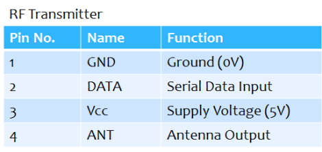
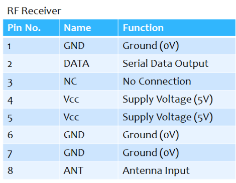
Now, let’s have a look at it’s pinout (courtesy EngineersGarage)

RF Module Pins
Pin Description:
Features:
- Range in open space(Standard Conditions) : 100 Meters
- RX Receiver Frequency : 433 MHz
- RX Typical Sensitivity : 105 Dbm
- RX Supply Current : 3.5 mA
- RX IF Frequency : 1MHz
- Low Power Consumption
- Easy For Application
- RX Operating Voltage : 5V
- TX Frequency Range : 433.92 MHz
- TX Supply Voltage : 3V ~ 6V
- TX Out Put Power : 4 ~ 12 Dbm
This has single channel for data transfer, thus serial data communication is used.
Serial Encoder/Decoder
The most popular serial encoder/decoder used is the HT12D-HT12E pair. Their description is given below. It’s okay if you don’t understand what is written there. Just make sure you go through the pin configurations and the circuit implementation.
The HT12E Encoder ICs are series of CMOS LSIs for Remote Control system applications. They are capable of Encoding 12 bit of information which consists of N address bits and 12-N data bits. Each address/data input is externally trinary programmable if bonded out.
The HT12D Decoder ICs are series of CMOS LSIs for remote control system applications. This ICs are paired with each other. For proper operation a pair of encoder/decoder with the same number of address and data format should be selected. The Decoder receive the serial address and data from its corresponding encoder, transmitted by a carrier using an RF transmission medium and gives output to the output pins after processing the data.
Features – Encoder
- 18 PIN DIP
- Operating Voltage : 2.4V ~ 12V
- Low Power and High Noise Immunity
- CMOS Technology
- Low Standby Current and Minimum Transmission Word
- Built-in Oscillator needs only 5% Resistor
- Easy Interface with and RF or an Infrared transmission medium
- Minimal External Components
Features – Decoder
- 18 PIN DIP
- Operating Voltage : 2.4V ~ 12.0V
- Low Power and High Noise Immunity
- CMOS Technology
- Low Stand by Current
- Ternary address setting
- Capable of Decoding 12 bits of Information
- 8 ~ 12 Address Pins and 0 ~ 4 Data Pins
- Received Data are checked 2 times, Built in Oscillator needs only 5% resistor
- VT goes high during a valid transmission
- Easy Interface with an RF of IR transmission medium
- Minimal External Components
Applications
- Burglar Alarm, Smoke Alarm, Fire Alarm, Car Alarm, Security System
- Garage Door and Car Door Controllers
- Cordless telephone
- Other Remote Control System
Compatibility
- Compatible with RF Modules 433 MHz Link RF Modules (Tx + Rx Pair) 433 Mhz ASK
Circuit Implementation
There isn’t much in circuit implementation. You just need to take a solderless breadboard and make the connections… and snap! You are done! 🙂
Transmitter Section
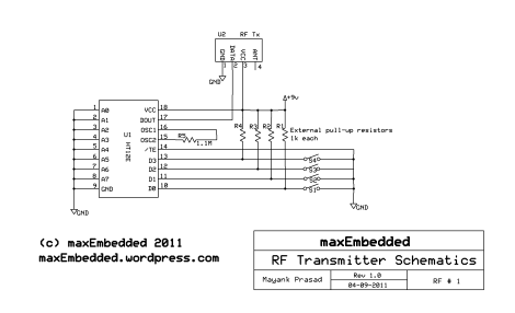
Make the following circuit on a breadboard. You are requested to implement the following circuit at your own risk! We will NOT be responsible for any damages caused due to implementation of the circuit, physically, mentally or financially.
Here, we have used four switches S1, S2, S3 and S4 to give 4-bit parallel data (D0-D3). Since the switches are in active low state (i.e. low signal is sent when the switch is pressed), we need to add external pull-up resistors as shown, so as to provide a high signal by default. A resistance as high as 1Mohm is required in between OSC1 and OSC2 pins. The Transmitter Enable (TE, pin 14) pin is an active low pin. Thus, it is permanently grounded, so as to enable the transistor always. The output serial data DOUT is fed to the RF Transmitter Module directly.
The most important thing lies in the address pins (A0-A7, pin1-8). Suppose you have two wireless devices (A and B) in your house, both have different remote controls (AA and BB) and both implement the same type of RF module (say 433 MHz). AA is the remote control of A and BB is of B. Now, you obviously wouldn’t want AA to control B (which is the most probable case since both the devices use same kind of RF module, having same frequency!). This is where address pins come into play. There are 8 address pins, thus giving you an opportunity to have 8! (8 factorial) different and independent ways to connect to a device, so that there is no interference. The address pins MUST have the same address in both transmitter and receiver, or else the data won’t be transferred. Refer to the receiver circuit for more details.
Receiver Section
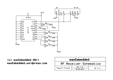
Now make the following circuit on a different breadboard. As mentioned earlier, you are requested to implement the following circuit at your own risk! We will NOT be responsible for any damages caused due to implementation of the circuit, physically, mentally or financially.
The circuit of the receiver is also quite simple. Capacitor C1 is used between Vcc and GND for noise filtering. Apart from that, all the address pins (A0-A7, pin 1-8) are grounded, just as in transmitter. This is to ensure that the transmitted data is being received. Both the transmitter and the receiver MUST have the same address pins configuration. Pin 17 (VT) is enabled whenever the receiver receives any data. The serial data received by the RF Receiver module is directly fed to pin 14 (DIN), which is then converted into 4-bit parallel data (D0-D3). A 33 kohm resistor is connected in between OSC1 and OSC2.
Antenna
Okay, so now that all the connections are made, you must choose an antenna for signal transmission. Usually, a 20-30 cm wire serves best. It is sufficient to give a range of 80 meters in open region. To improve the efficiency, you can also use a coiled wire (take a wire and make it into a coil). It increases the signal strength.
Result – What you will get?
Once the circuit is made and powered up, the four LEDs on the receiver end will glow by default. The LED corresponding to VT glows only when some data is received. Now whenever you press any switch (on the transmitter end), that particular LED (on the receiver end) goes off! Interesting, eh?! 😉
Troubleshooting
It’s obvious that you won’t get the result in the first go itself! It’s completely normal, even in my case! 😀 There will be times when you will say to yourself that it’s not gonna happen. In that case, just try out the simple wired communication. Connect the DOUT of the encoder directly to the DIN of the decoder using a wire. Then check and recheck your connections, check whether the address is the same, whether you have missed any Vcc or GND connection, etc. If still then a successful link is not established, change your encoder/decoder ICs. Once your link is established, connect the RF module and do the same. Try adjusting the antenna position, touch the antenna (touching the antenna will make yourself an antenna!), etc. If still not successful, then all I suggest is to google out your problem and see if somebody else has sorted it out or not.
Extending the circuit
This circuit can be easily extended to anything, depending upon your application. If you are using it control a robot, the output data can be directly given to a motor driver. View this article for details. If you are using it to control any external device, this data can be fed there. In other words, whatever data you wanted to send, the same is available at some other location, which can be manipulated very easily.
Making an RF Car
If you want to make a wireless robot and want to use RF technology to achieve that, then you can view this interesting post by Yash on maxEmbedded and learn how he made it.
So folks, this is all about RF module interfacing without using microcontrollers. We will discuss the same topic once again after learning Serial Communication. So till then, you can stay updated by grabbing RSS Feeds or subscribing to my blog! 🙂
Thank You
Mayank Prasad
VIT University


Hai may i know how the receiver translate the data to give the PIC after it received data from the transmitter n what kind of data that remote control sent. Tq
Hi Mickha
First of all the RF technology which is used in RF TxRx, uses amplitude shift keying(ASK) techniques which is a binary or better to say digital form
of amplitude modulation(AM) technique for transmitting the data from Tx to Rx.
At the receiver end the data when received, is filtered first and then demodulated so as to get back the original signal.
hello.
can any body send me a complete documentation about rf module..?
my email id:sriakhileshp@gmail.com
Hello Akhilesh
What documentation do you require? The Pin Descriptions?
concept of using encoder and decoder in rf module.
Encoder/Decoders are an alternate to Interfacing the RF Modules with an MCU with the help of UART. In other words, they make your work simpler by eliminating the coding part.
Reply back if you need any more help!
Hi to all, how is everything, I think every one is getting more from this site, and
your views are nice for new viewers.
hi, can we interface the above set -up with a micro-controller so that we can assign another hardware for usart/uart.. ?? i’m asking that instead of that switches can we directly connect encoder/decoder wires into port pins.. will it be working fine..?
Hi Rakesh,
I can’t find any reason why it won’t.
Hello,
i am using pc controlled application.
I have made max232 circuit to get serial output from UART.
I have connected ask transmitter data pin to max232 serial tx.
and ask receiver is connected to my microcontroller P3.0(rx pin).
But this is not working fine.
I checked by directly connecting wire(without ask) then its working fine.
What should i do?
Thanks
Darpan, did you try playing around with the antenna?
Hello Mayank,
I have checked the antennas on another application using encoder and decoder ic, antennas are working fine..
The problem comjes when i interface with UART.
Hello
can anyone help me… i have constructed transmitter and reciever circuits on two different pcb. the transmitter side is working well as i have seen the waveforms on CRO.. but on reciever side the reciver is recieving is recieving the same waveform but decoder is not working(Vt not going high).
i tried no. of combinations of resistance(b/w osc1 &osc2) but didnt work
1- 1Mohm on tx side & 33k on rx
2-1Mohm on Tx side & 1k on Rx
3-820 K on Tx side & 1k in Rx..
please help..
i’ve grounded all the address pin in both HT12E & HT12D…
ive also replaced the HT12D but it doesnt worked at all…
great post brother… 🙂
i think that the LED’s placed at the data lines of decoder should be connected in a way such that the negative of LED is connected to the data pin and positive of LED connected to VCC.
Still it is a good tutorial for teaching the basics of rf module interfacing without microcontrollers… :))
It doesn’t matter. You’re describing active low configuration, whereas I used active high. Both are a complement of each other. Thanks.
dear sir i ysed positivte control but its still not working what is the region
I’m sorry, what?